Expose Kubernetes Microservices hosted on Private Subnets and On-Premises Networks
Part 1. AWS Architecture Diagram
Table of contents
Introduction
Microservices
Microservices enable applications to scale easily and to develop quickly, thus enabling innovation and speeding up time to market. The two main technologies that enable the development of microservices applications are Containers and Serverless. In recent years, Kubernetes (K8s) has been widely adopted for automating the deployment of infrastructure, scaling of resources, and managing containerized applications.
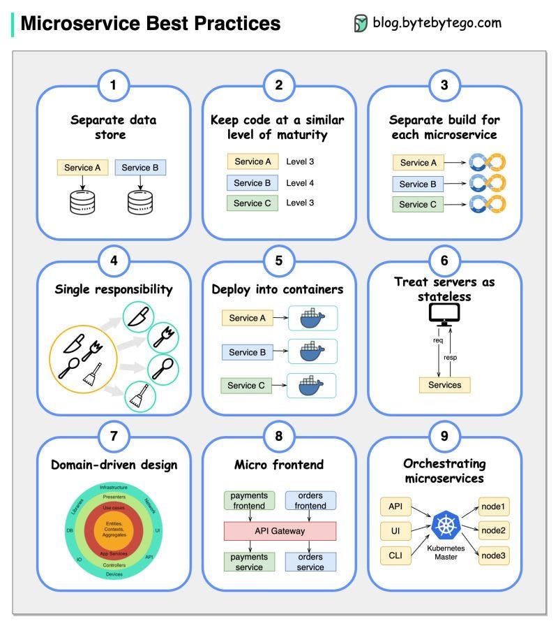
When we develop microservices, we need to follow the following best practices [1]:
Use separate data storage for each microservice
Keep code at a similar level of maturity
Separate build for each microservice
Assign each microservice with a single responsibility
Deploy into containers
Design stateless services
Adopt domain-driven design
Design micro frontend
Orchestrating microservices

Amazon Elastic Kubernetes Service (EKS)
Utilize Amazon EKS to expose K8s Microservices hosted on private subnets to the Internet and on-premises networks.
Terraform
Further, HashiCorp Terraform Infrastructure as Code is a tool to deploy and operate containerized workloads quickly and efficiently.
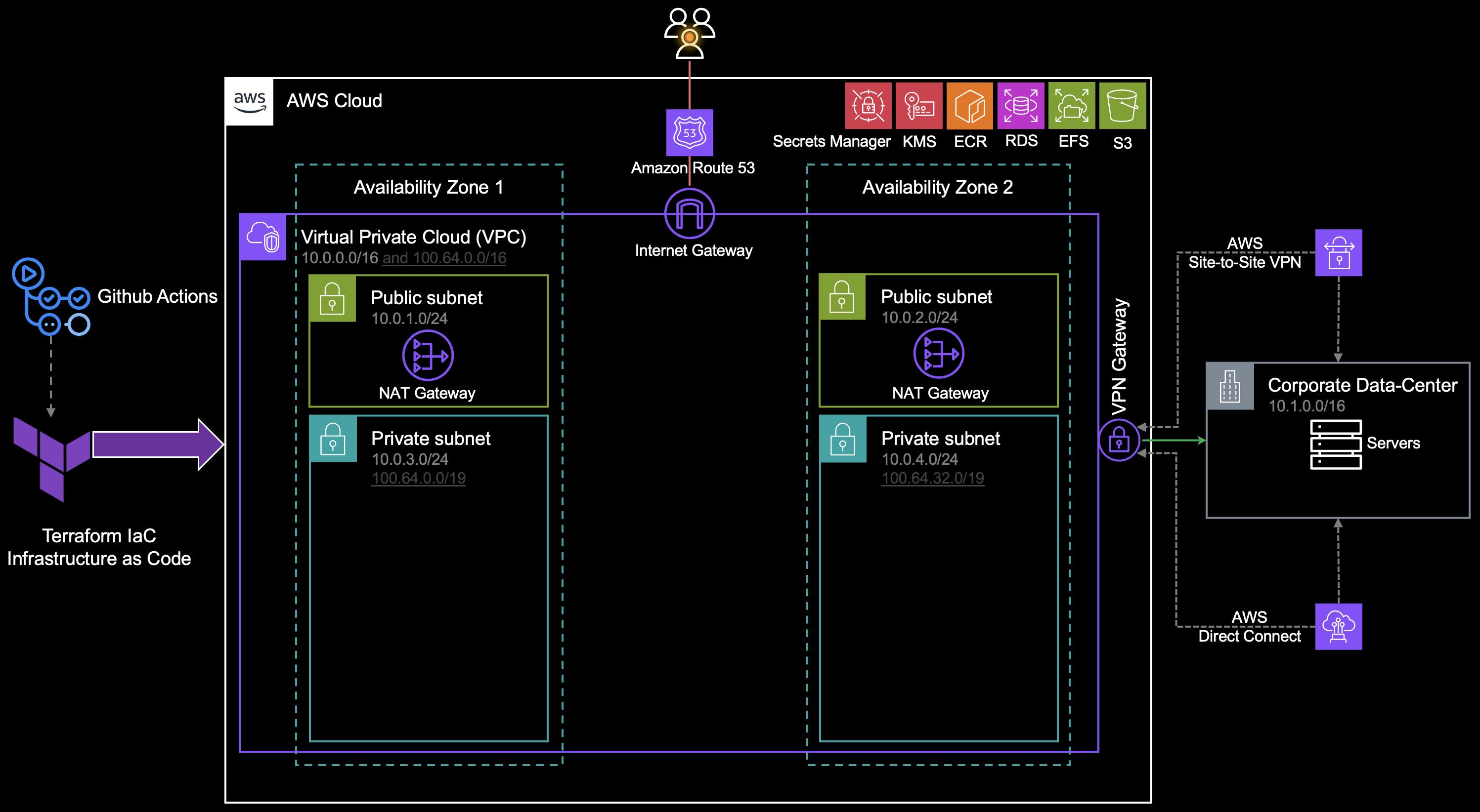
Virtual Private Cloud (VPC)
A highly available architecture that spans at least 2 Availability Zones.
A VPC configured with public and private subnets, according to AWS best practices, to provide you with your own virtual network on AWS.
Routes incoming internet traffic through an Amazon Route 53 public hosted zone.
In the public subnets, managed Network Address Translation (NAT) gateways allow outbound internet access for resources in the private subnet.
In the private subnets, Amazon EKS clusters with Kubernetes Worker Nodes -inside an Auto Scaling Group. Each node is an Amazon Elastic Compute Cloud (Amazon EC2) instance or AWS Fargate. Each cluster may contain the following:
Microservices applications and components.
Cert-manager.
An open-source logging and monitoring solution with Grafana, Prometheus.
ExternalDNS, which synchronizes exposed Kubernetes services and ingresses with Route 53.
An Elastic Load Balancer to distribute traffic across the Kubernetes nodes.
Amazon Simple Storage Service (Amazon S3) to store the files.
Amazon Elastic File System (Amazon EFS) to provide storage for Grafana, Prometheus.
Amazon Relational Database Service (Amazon RDS) for PostgreSQL to store application data.
Amazon Elastic Container Registry (Amazon ECR) to provide a private registry.
AWS Key Management Service (AWS KMS) to provide an encryption key for Amazon RDS, Amazon EFS, and AWS Secrets Manager.
AWS Secrets Manager to replace hardcoded credentials, including passwords, with an API call.
🚦 The traffic is sent/receive to/from the on-premises network over the Virtual Private Network (VPN) or AWS Direct Connect connection.

Expose Microservices in a Hybrid Scenario
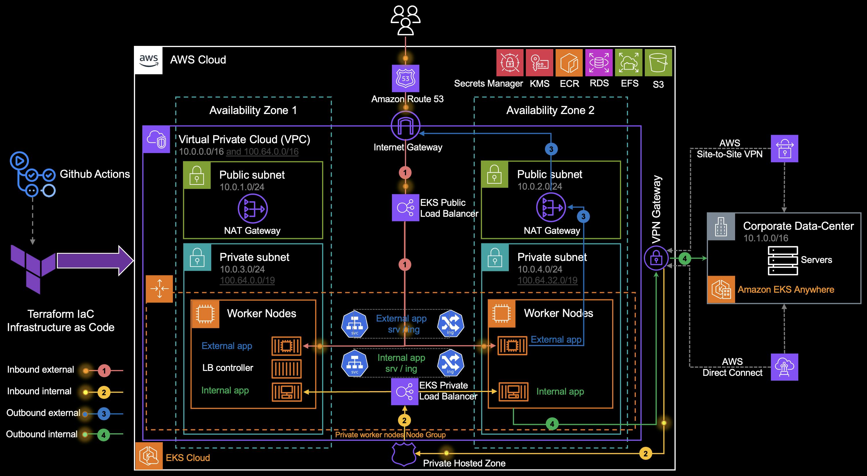
1. Inbound External & EKS Public Load Balancer
Amazon Route 53 resolves incoming requests to the public Elastic Load Balancer (ELB) deployed by the AWS Load Balancer Controller.
🚦The AWS LB controller satisfies K8s services with Network Load Balancers (NLBs) and Kubernetes ingresses with Application Load Balancers (ALBs). You can also manage ingresses by implementing other ingress controllers like the NGINX ingress controller.
🚦The EKS-related ELBs forward traffic to applications. You can choose between the two modes [2]:
Instance mode: The traffic is sent to a worker node, then the service redirects traffic to the Pod.
IP mode: The traffic is directed to the IP of the Pod directly.
🚦If we’re using AWS Fargate for Amazon EKS, we will not have Worker Nodes but only the pod ENIs in the private subnets. You can only use ELBs with IP mode with AWS Fargate pods.
2. Inbound External & EKS Private Load Balancer
- Amazon Route 53 resolves incoming requests to the Private ELB deployed by the AWS Load Balancer Controller.
3. Outbound External
When the pod in private subnets initiates an outbound request to the internet, the private route table forwards the traffic to the NAT Gateway (NGW).
The public route table forwards the traffic from the NGW to the Internet Gateway (IGW).
4. Outbound Internal
The pod in private subnets initiates an outbound request to the on-premises network. The private route table forwards the traffic to the Virtual Private Gateway (VGW).
🚦 You can also enable private access for your Amazon EKS cluster’s Kubernetes API server endpoint and limit, or completely disable, public access from the internet [3].

🚦Deal with Pod IP Exhaustion:
Increase the IP addresses available to pods by adding dedicated subnets from the 100.64.0.0/10 and 198.19.0.0/16 ranges.By adding secondary CIDR blocks to a VPC from the RFC 6598 address space (in the example 100.64.0.0/16), in conjunction with the CNI Custom Networking feature, it is possible for pods to no longer consume any RFC 1918 IP addresses in a VPC (in the example, pods are in subnets 100.64.0.0/19 and 100.64.32.0/19). Check out How do I use multiple CIDR ranges with Amazon EKS?
💡 Moving to IPV6 also solves pod IP exhaustion, because you don’t need to work around IPv4 limits.
🚦Check out EKS VPC routable IP address conservation patterns in a hybrid network for Multi-Account settings to leverage the AWS Transit Gateway to scale this pattern across an enterprise to include multiple EKS clusters and an on-premises data-center.